(1) Frictional pressure drop shall be calculated using the Darcy-Weisbach equation as follows: 3.1.2 Pressure drop Calculation formula used in Hydraulic Calculation: (4) In revamping or modification projects of the existing plant, the fluid velocity is more likely to be increased than in new installation projects.(3) In some instances, the process requirements will take precedence over the economical aspects for example, in the case of pump suction lines where the NPSH is the main concern.(2) However, line sizes should not exceed the limitations given in project specifications.(1) The basic principle to fix the line sizes during performing hydraulic calculation should be based on an economical point of view, i.e., minimizing the sum of operational costs and investment.3.1.1 Basic Principle for Line Sizing used in Hydraulic Calculation: The basic principle to fix the line sizes should be based on an economical point of view, i.e., minimizing the sum of operational costs and investment. If it has been observed in a hydraulic calculation that the pressure drop & velocity exceed the limiting criteria given in project criteria then line size can be increased & it is subjected to the client’s approval. As the main parameters that are used to check are pressure drops & velocity. Pressure losses through the pipeline should be carefully calculated. So in a hydraulic calculation, the whole loop needs to be developed as per P & ID. (1) As we know, pumps’ & compressors’ capacity, power & requirements of head depend on the frictional pressure drop imparted by the associated piping system. Hydraulic Calculation & Formulas 3.1 General: – Turndown % – specification of the minimum flow rate, if any 3.– Over design % – specification of the design flow rate, if any.The design data will be obtained from, but not limited to, the following documents The data to be used for the hydraulic calculation, such as the flow rate, temperature, pressure, and so on should be clarified as follows. 2.1 What are data required for hydraulic calculation?


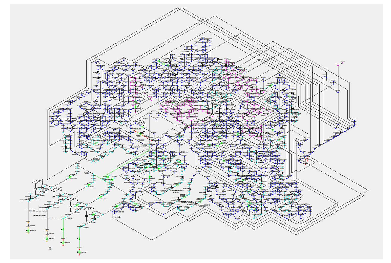
For hydraulic calculation, a Hydraulic circuit needs to be built prior to hydraulic calculation.


 0 kommentar(er)
